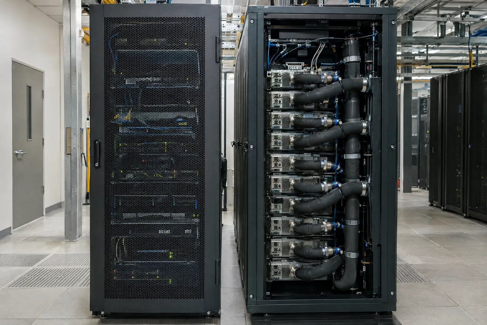
The Uptime Institute's 2025 survey found that 67% of existing data centers cannot support modern GPU power density. This isn't a capacity planning failure. It's physics: traditional facilities were engineered for 10 to 15 kW per rack, and AI accelerators now require 40 to 75 kW per rack.
Understanding why this matters requires examining the thermal, electrical, and mechanical engineering challenges inherent in high-density GPU deployments.
The Power Density Challenge
GPU Thermal Output: The Physics
NVIDIA's H100 GPU has a Thermal Design Power (TDP) of 700W. The H200, optimized for inference workloads, maintains similar thermal characteristics. These numbers represent continuous heat generation during operation, not peak or burst loads.
| Component | Thermal output |
|---|---|
| 8 GPUs at 700 W each | 5,600 W |
| CPU, RAM, storage | 800 to 1,200 W |
| Networking (2x 400GbE) | 200 to 400 W |
| Total per 2U server | 7,000 to 8,000 W |
| Full 42U rack (10 servers) | 70 to 80 kW |
Traditional data center design assumes 10 to 12 kW per rack. Enterprise facilities might reach 15 kW per rack with enhanced cooling. GPU racks require 40 to 80 kW per rack, a 4 to 7x increase in thermal density.
Why Traditional Air Cooling Fails
Computer Room Air Conditioning (CRAC) Limits
Traditional CRAC units work by circulating chilled air through raised floors and extracting hot air from hot aisles. This approach has physical limitations dictated by airflow dynamics and heat transfer efficiency.
Beyond 15 kW per rack, air cooling requires unrealistic airflow volumes. A 40 kW rack would need approximately 4,000 CFM at a 20°F delta T. This creates:
- Excessive fan power consumption
- Acoustic levels exceeding OSHA workplace limits
- Hotspots where airflow cannot reach all components
- PUE (Power Usage Effectiveness) degradation as cooling overhead increases
Liquid Cooling: Engineering Requirements
Direct-to-Chip Liquid Cooling
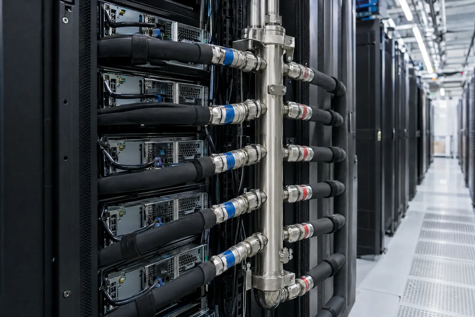
Liquid cooling uses water or water-glycol mixtures to absorb heat directly from GPUs via cold plates. Water's specific heat capacity (4.186 kJ/kg·K) is 4,000x higher than air, enabling efficient heat transfer with minimal flow rates.
Hybrid Cooling Architectures
Most 40 kW and above GPU deployments use hybrid cooling: liquid for GPUs, air for everything else (CPUs, memory, network switches). This pragmatic approach addresses the highest thermal density sources with liquid while maintaining simpler air cooling for lower-power components.
| Cooling Method | Max Density | PUE Impact | Complexity |
|---|---|---|---|
| Traditional CRAC | 10 to 15 kW per rack | 1.5 to 1.7 | Low |
| In-Row Cooling | 15 to 25 kW per rack | 1.4 to 1.6 | Medium |
| Rear Door Heat Exchangers | 25 to 35 kW per rack | 1.3 to 1.5 | Medium |
| Hybrid (Liquid GPU + Air) | 40 to 60 kW per rack | 1.2 to 1.3 | High |
| Direct-to-Chip (Full Liquid, cold-plate DLC) | 60 to 200 kW per rack | 1.05 to 1.2 | High |
Electrical Infrastructure for GPU Density
Power Distribution Architecture
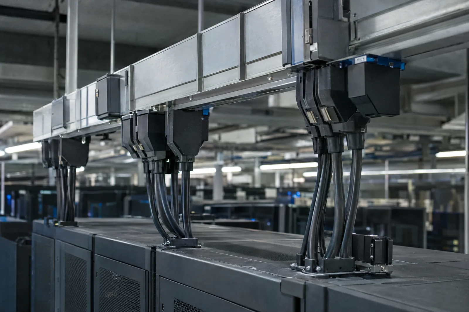
GPU racks require purpose-built electrical infrastructure to deliver 40 to 80 kW reliably. This necessitates three-phase power distribution, proper voltage levels, and careful attention to power quality.
Power Quality Considerations
- Power Factor Correction: GPU servers can have power factors of 0.85 to 0.95. Active power factor correction (PFC) in power supplies improves this, but reactive power management remains critical at scale.
- Harmonic Mitigation: Switch-mode power supplies generate harmonic currents, primarily 3rd, 5th, and 7th harmonics. K-rated transformers and harmonic filters prevent overheating of electrical distribution components.
- Voltage Sag Tolerance: GPU training runs can last days or weeks. Power supplies must tolerate brief voltage sags (brownouts) without triggering shutdowns. Typical requirement: withstand 10% voltage sag for 50ms.
Redundancy and Resiliency
GPU infrastructure typically requires N+1 or 2N power redundancy depending on criticality:
Power Usage Effectiveness (PUE) Optimization
PUE measures data center efficiency: total facility power divided by IT equipment power. Lower is better. Traditional air-cooled facilities achieve PUE of 1.5 to 1.7, meaning 50 to 70 percent overhead for cooling, lighting, and electrical losses.
For a 1 MW GPU facility, the difference between PUE 1.5 and PUE 1.2 represents 300 kW of reduced overhead. At $0.10/kWh and 80% utilization, this saves approximately $210,000 annually in electricity costs.
Design Checklist for 40 kW and above GPU Deployments
Engineering Determines Feasibility
The engineering challenges of 40 kW and above GPU racks are not hypothetical. They represent physical constraints that dictate which facilities can support modern AI infrastructure.
Traditional data centers designed for 10 to 15 kW per rack cannot simply add more cooling. The thermal transfer requirements, electrical distribution demands, and power quality considerations require purpose-built infrastructure.
Organizations deploying GPU infrastructure must verify that their facilities can handle the thermal density, electrical load, and cooling requirements before procurement. The engineering determines feasibility, not the budget.