Technical Specifications
Three sizes of factory-built, liquid-cooled AI capacity: 1.6 MW, 4.8 MW and 9 MW.
Three sizes, one platform
Each size is a complete, repeatable unit of liquid-cooled capacity with its own power path, battery storage and cooling plant.
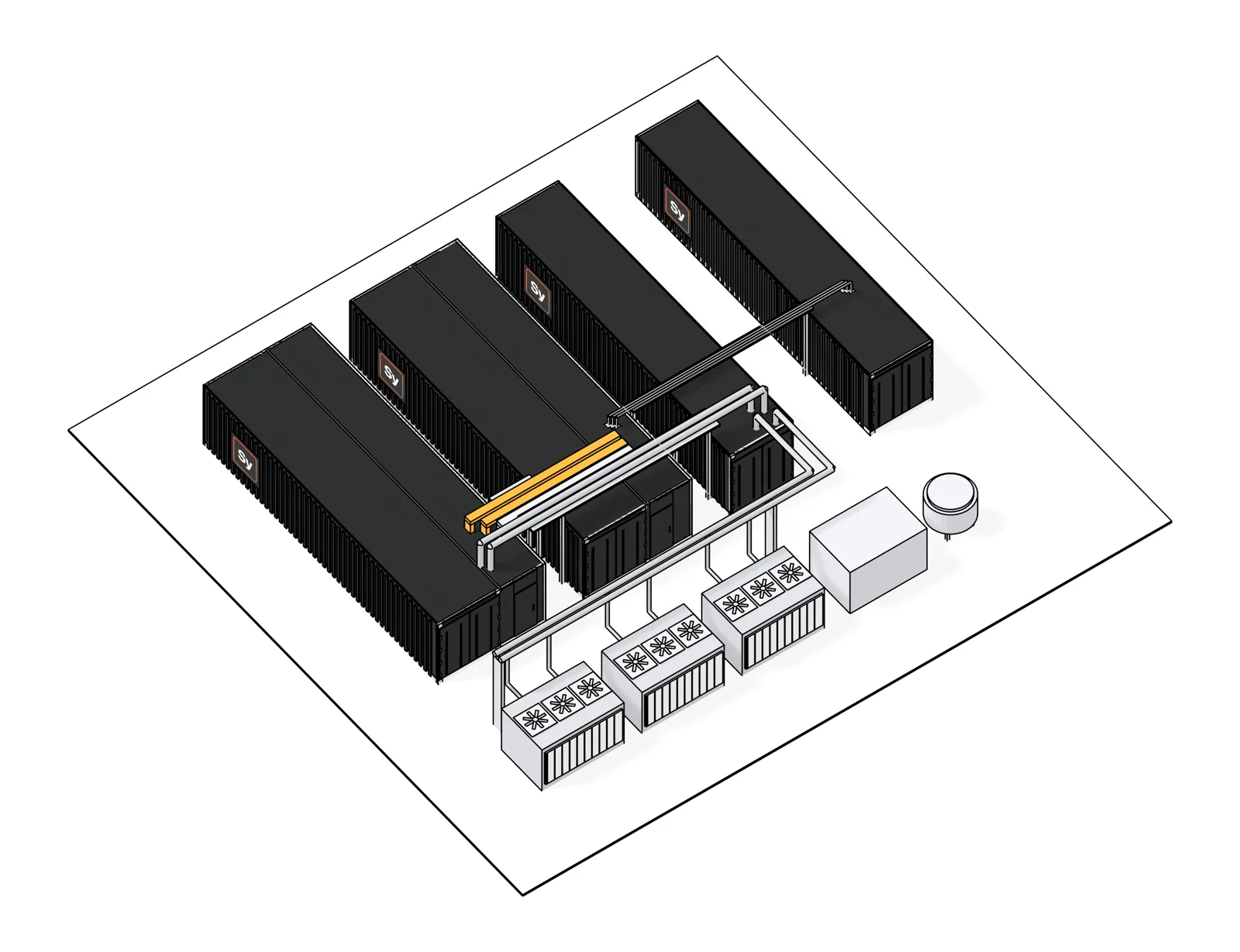
1.6 MW Block
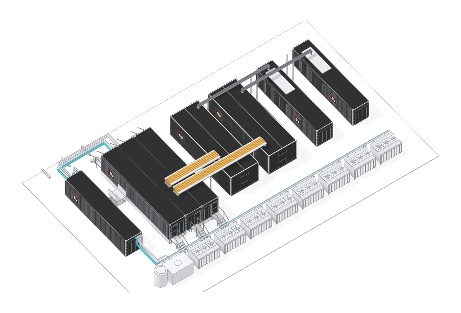
4.8 MW B300 Block
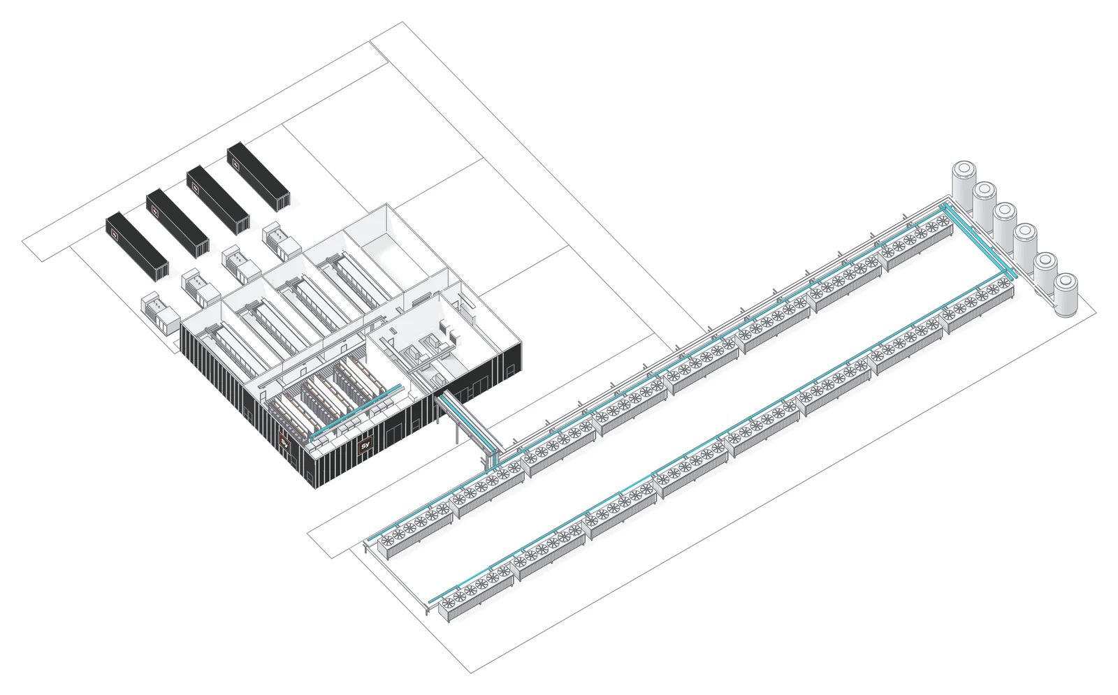
9 MW Liquid-Cooling Zone
| 1.6 MW Block | 4.8 MW B300 Block | 9 MW Zone | |
|---|---|---|---|
| Design capacity | 1.6 MW | 4.8 MW | About 9 MW |
| Rack positions | 8 | 32 | 66 bays in three pods |
| Density per position | Up to 200 kW | 150 kW | 150 kW GB300; up to 250 kW Vera Rubin |
| Power redundancy | N+1; 2N with separate A and B paths | N+1 in each half of the block | N+1 by path: any one of four paths can be out |
| Cooling | Direct-to-chip warm-water loop | Direct-to-chip, in-rack distribution and rear doors | Direct-to-chip warm-water loop, contained hot aisle |
| Starting point | One block | One block | Opens in thirds, from 3 MW |
Blocks and zones add in place on the same site, from one block to a 50 MW campus. Typically 4 to 8 months from order to ready for service, depending on equipment reservation and site readiness.
Factory-built modules, each with one job
Site power is conditioned, backed by battery and delivered to the racks; warm water carries the GPU heat out to the coolers. Modules are built and tested in the factory and joined on site.
| Module | 1.6 MW Block | 4.8 MW B300 Block | 9 MW Zone |
|---|---|---|---|
| IT | IT module: 8 rack positions, busway, water manifolds, in-row air units, clean-agent fire suppression | IT room: two rack wings and a central service spine, water below, power above | Hall of three pods: 66 rack bays, contained hot aisles, fan walls |
| Power | Power module: UPS and distribution, N+1 | A power module for each half, N+1 | Four power paths, each a substation, UPS and distribution |
| Energy storage | Energy storage module, LFP battery strings | Energy storage for each half, serviced from outside | A battery enclosure for each path |
| Pumps | Pump module, warm-loop pumps N+1 | Pump module, warm-loop pumps N+1 | Cooling train, warm-loop pumps 2+1 |
| Heat rejection | Dry coolers, N+1 | Dry coolers, N+1 | Adiabatic coolers with spare capacity |
| Residual air | Chilled water from a site source | Chilled-water rear doors from a site source | Chillers 2+1 in the zone plant room |
Electrical Infrastructure
Redundant power paths, battery-backed, built for continuous operation under full GPU load.
| Parameter | Specification | Notes |
|---|---|---|
| Input, blocks | 480 V class (1.6 MW), 415 V class (B300) | Low voltage from the site transformer |
| Input, zone | Medium voltage | Into the zone's own substations, one per power path |
| Power conditioning | Online double-conversion UPS | High-rate battery bridge, one battery string per power module |
| Battery storage | Lithium iron phosphate | Designed to UL 9540 and NFPA 855; bridges the transfer to site generation |
| Distribution | Overhead busway to every rack position | A and B busway in the blocks; four sources per rack in the zone |
| Generation | Generator-ready | Site generation is sized per site and connects at the module interface |
| Monitoring | Integrated building management | Power and cooling monitoring across the modules |
Thermal Management
Direct liquid cooling to the cold plate on a warm-water loop, from 130 kW to 250 kW per rack.
| Parameter | Specification | Notes |
|---|---|---|
| GPU heat | Direct liquid cooling to the cold plate | Propylene-glycol warm-water loop |
| Loop temperatures | Facility supply 35 to 40 C | Warm water lets dry and adiabatic coolers reject the heat |
| Residual air heat | Separate chilled-water circuit | Rear doors, in-row units or fan walls, with redundant units |
| Exhaust air | Contained rack exhaust aisle | Hot air stays out of the room |
| Heat rejection | Dry and adiabatic coolers | Spare capacity built in; no cooling towers |
Rack platforms supported
Rack count and density are set within each size's design capacity. Zones can mix rack platforms pod by pod.
| Rack platform | Density per rack | Cooling at the rack | Supported on |
|---|---|---|---|
| GB300 NVL72 class | 130 to 150 kW | Cold plates, in-rack cooling distribution | 1.6 MW Block (positions to 200 kW), 9 MW Zone |
| HGX B300, liquid cooled | 150 kW | Cold plates, in-rack distribution, chilled-water rear door | 4.8 MW B300 Block |
| Vera Rubin NVL72 class | Up to 250 kW | Cold plates, pod cooling distribution | 9 MW Zone, by pod |
Densities are indicative design values and vary with rack selection, GPU generation and site conditions.
N+1 standard, 2N on the 1.6 MW Block
The load is carried with any one power module, path, pump or cooler out of service. The utility feed and site generation are sized per site as N, N+1 or 2N.
| 1.6 MW Block | 4.8 MW B300 Block | 9 MW Zone | |
|---|---|---|---|
| Power and battery | N+1 power modules, one battery string each; 2N option | N+1 per half, battery storage per half | Four independent paths, any three carry the zone; battery per path |
| Coolant pumps | N+1 | N+1 | 2+1 |
| Heat rejection | N+1 coolers | N+1 coolers | Spare cooler capacity |
| Residual air cooling | N+1 in-row units | Rear doors; N+1 trim units | Chillers 2+1, fan walls and gallery units |
With one power module out for service, the 1.6 MW Block runs at N. Redundancy descriptions refer to the design and are not an Uptime Institute certification.
Codes and standards
Each size is designed to the US codes below. Third-party evaluation is arranged per project.
NEC
National Electrical Code for power distribution and working space
UL 9540 and NFPA 855
Energy storage systems: listing basis and installation
ASHRAE TC 9.9
Thermal guidelines for data processing environments, recommended envelope
NRTL evaluation
Field evaluation by a nationally recognized testing laboratory, arranged for each deployment
"Designed to" describes the engineering basis; certification is confirmed per project.
Need specifications for your site?
Site data sheets and technical packs are shared under a mutual NDA. Tell us the rack platform, the target megawatts and the site.